becomes rainy weather, the cable is prone to water flooding, and the harm is great, how to solve it?
Solution
1 Try to secure the cable with the highest bracket possible
2. Do a good job of drainage measures in the cable shaft.
3. NKTEVA6 monitoring device is installed in the cable shaft,
with its own water immersion sensor, and the cable is flooded with alarm, and the engineers drain the water in time
Video capture is also possible, and the cable can also be monitored for overheating
The intelligent distributed red array monitoring and detector NKTEVA6 cable flood alarm is equipped with software
The new version adds a flood alarm function (with a water immersion sensor), and the field of view of the red array is 90 degrees
Wide field of view, very suitable for transformer/high and low voltage cabinet monitoring and cable tunnel comprehensive pipe gallery fire monitoring
Red Array video can be recorded and captured
The new version of the Red Array has a wider field of view of 90 degrees
Network powered/POE-powered fixed installation
The Red Formation responds faster
One computer on the host computer workstation can run multiple sets of monitoring software at the same time
Internet exaggeration browsing
Windows PC ANDROID phone
Mobile browsing is faster
TS501-94 Distributed Red Array Detector
TS501-95 Red Array Controller 8/16 ports
.jpg)
Comes with LED
NKTEVA6 Distributed Red Array Detector Monitoring Software 2025 Version Instructions for Use
No software installation required Does not occupy the registry Safer Less system resources Faster Runs can be run by unzipping
1 set of red array monitoring and display management software
1 set of over-temperature alarm, cable flooding alarm
(One computer can install multiple sets of software on the host computer workstation and run at the same time)
2 Red Array Controller NKTP 1 set A single NKTP Red Array controller has a maximum of 24 ports of RJ45 power supply and communication
3 Distributed red array detector NKTEVA6 1 set with water seepage sensor and red array detector 256×192 field of view 90 degrees,
(supports Windows PC ANDROID phone browsing and settings).
Real-time, continuous, and easier to use RJ45 network power supply interface, the wiring is simpler and relatively safer
Ideal for large network systems
Wide field of view, very suitable for high and low voltage cabinet monitoring and cable tunnel comprehensive pipe gallery fire monitoring
Provide advanced red array detection temperature imaging video surveillance solutions for on-site condition monitoring:
The new VOx detector can be used to resolve more details; 25Hz frame rate network interface; More advanced Matrix III. image algorithm;
Reduced size and power consumption, easy to install; Compatible with multiple industrial protocols, easy to realize automatic alarm, and compatible with power monitoring SCADA interconnection
|
Product model
|
NKTEVA6
|
|
detector
|
Uncooled IR Focal Plane Detector 256×192 (greater than 43,200 IR dot matrix).
|
|
Thermal sensitivity
|
<40mk(@25℃,F=1,25Hz)
|
|
Frame rate
|
25fps
|
|
Red Formation Field of View
|
The wide field of view of the red formation is 90°×65.1°/
|
|
palette
|
At least 6 color palettes (Hot Black/White Heat/Iron Red/etc.)
|
|
Visible light parameters ultra-wide field of view 120°
|
|
resolution
|
1600×1200 wide field of view 120°/
|
|
Fill in the light
|
Built-in LED light
|
|
Multispectral fusion
|
|
Visible light fusion
|
Dual-band image fusion enhancement
|
|
Temperature measurement
|
|
Temperature measurement range
|
Supports wide dynamic -20 °C to +550°C)
|
|
Temperature measurement accuracy
|
±2°C or 2% of the range (2% of the range in a wide dynamic state)
|
|
Point temperature measurement
|
12 movable points for temperature measurement, which can be used for the highest and lowest temperatures of other temperature measurement points or temperature measurement areas,
Average temperature comparison (up to 48 points or lines or zones at the same time).
|
|
Regional temperature measurement
|
12 movable zones for temperature measurement, with maximum, minimum and average temperatures in the zones,
It can be compared with the maximum, minimum temperature and average temperature of other temperature measurement points or temperature measurement areas
(Up to 48 points or lines or zones at the same time)
|
|
Linear temperature measurement
|
1 line for temperature measurement, with the highest, lowest and average temperatures on the line
(Up to 48 points or lines or zones at the same time)
|
|
Reference humidity
|
Manual setup
|
|
Atmospheric transmission correction
|
Automatic, input values based on distance, atmospheric temperature, and relative humidity
|
|
Emissivity correction
|
0.01 to 1.0
|
|
Reflection apparent temperature correction
|
Automatic, based on reflected temperature input
|
|
Temperature measurement correction
|
Population and individual target parameters
|
|
alarm
|
|
Alarm function
|
The maximum and minimum temperatures at all temperature measurement points, all temperature measurement areas and within the temperature measurement line
and average temperature can be configured with individual alarm outputs
|
|
Alarm output
|
I/O output, light alarm
|
|
agreement
|
|
In the tank
|
ONVIF GB/28181 MQTT SDK is supported: Up to 8 concurrent users can be used
|
|
Image streaming
|
|
Image streaming format
|
MJPEG/H.264
|
|
Image storage
|
|
storage media
|
Built-in memory (Flash)
|
|
file format
|
JPEG、MP4
|
|
Set up
|
|
There is a B/S configuration interface B/S
|
There is a C/S configuration tool called C/S
|
|
SDK
|
The original temperature data is output externally, and users can carry out secondary development
|
|
power supply
|
|
POE 802.3 at
|
The power consumption is less than 2.6W
|
|
External interface
|
|
NKTEVA6
|
Contains 10M/100M adaptive Ethernet port and POE power supply
|
|
Environmental parameters
|
|
Protection level
|
IP67
|
|
Operating temperature
|
-20℃ to +60℃
|
|
Storage temperature
|
-40℃ to +70℃
|
|
humidity
|
≤95%
|
|
Electromagnetic compatibility
|
EN 61000-6-2:2001(抗干扰) EN 61000-6-3:2001
FCC 47 CFR Part 15 Class B (Radiation Resistance)
|
|
Impact resistance
|
25G, IEC68-2-29
|
|
Vibration resistance
|
2G, IEC68-2-6
|
|
Physical parameters
|
|
size
|
93×56× 31.5 mm (without connector) Weight 160g
|
|
Accessories (not standard)
|
Interface cables, brackets, heat sinks
|
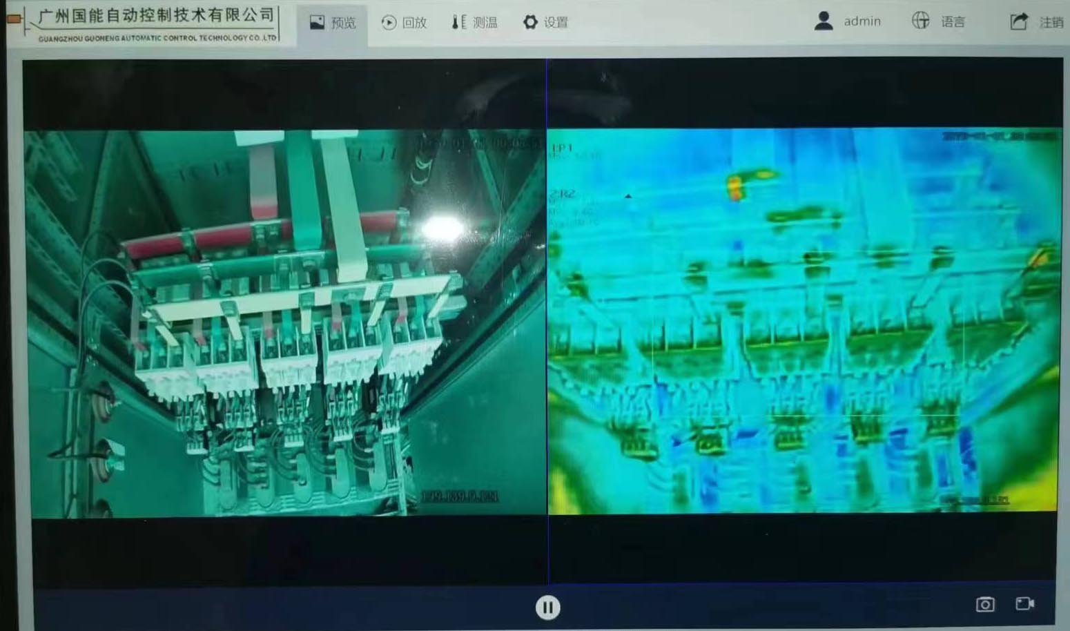
The distributed red array detector is an instrument that visualizes the temperature through the red array lens, and the video uploaded by the red array lens can be recorded and captured.
The distributed red array detector also has its own visible light lens, which can also be recorded and captured, compared with the visual temperature video and confirmed the location of the fault point.
The role of distributed red array detectors and the importance of installing them on power equipment
At present, the online monitoring of electrical equipment is paying more and more attention, because most of the electrical equipment is now unattended.
And with the increase of system capacity and customers' higher and higher requirements for power supply reliability, it is more necessary than ever to strengthen the detection and maintenance of equipment to eliminate accidents in the bud.
Distributed red array detector is a kind of equipment that uses modern high-tech means to conduct non-damage and non-contact detection of operating equipment.
Infrared visual temperature measurement and detection of running power equipment is judged by comparative methods in most cases. Normal operation of power equipment will generate heat due to the action of current and voltage.
When power equipment is defective or faulty, the temperature rise of the defective part will change significantly.
External thermal defects of power equipment According to the long-term measured data provided by relevant units and the comprehensive statistics of a large number of cases, the main causes of external thermal defects of power equipment are as follows:
(1) The joint is poorly connected, and the bolt is not pressed.
(2) Corrosion oxidation due to long-term operation due to conductor contact.
(3) Corrosion caused by harmful gases and dust in the atmosphere.
(4) Poor material quality and poor processing and installation technology cause conductor damage.
(5) The actual cross-section of the conductor is reduced due to mechanical vibration and other reasons.
(6) The load current is unstable or exceeds the standard or there is a large harmonic current.